The smart Trick of Wedge Barriers That Nobody is Talking About
Table of ContentsOur Wedge Barriers StatementsThe 20-Second Trick For Wedge Barriers


18 may be done more promptly, easily, and cost successfully. FIG. In particular personifications, the support 30 might be a steel framework consisting of plates, light beams(e. g., I-beams ), and/or other structures that are protected within the foundation 14, which might be concrete. At the surface area 12, an upper side 28 of the anchor 30 may go to the very least partially revealed
, thereby enabling the accessory of the obstacle 10 to the support 30. g., threaded holes)in one or even more light beams or plates of the support 30 may be revealed to the surface area 12. In this manner, bolts 32 or other mechanical bolts might be used to secure the barrier 10 to the anchor 30. As the obstacle 10 is installed to the surface 12 of the structure 14, collection of debris and other material below the obstacle may be decreased, and parts of the bather 10 may not be revealed to listed below grade environments. As shown by reference numeral 52, the training system 50 includes components disposed underneath the wedge plate 16. For example, the parts 52 under the wedge plate 16 may consist of an electromechanical actuator, a webcam, several web cam surface areas, and so forth. Furthermore, the lifting mechanism 50 includes a springtime assembly 54
The spring pole 58 is combined to a webcam(e. g., camera 80 received FIG. 4) of the lifting device 50. The springs 60 disposed about the springtime pole 58 are held in compression by springtime supports 62, consisting of a repaired springtime assistance 64. That is, the fixed springtime support 64 is dealt with about the foundation 14 and the remainder of the bather 10.
Wedge Barriers Things To Know Before You Buy
g., springtime assistance 65 )might be fixed to completion of the spring pole 58 to make it possible for compression of the springs 60. As the springtimes 60 are pressed between the springtime supports 62, the spring assembly 54 generates a pressure acting upon the camera combined to the springtime rod 58 in a direction 66. For instance, the continuing to be force related to
the cam to deploy the wedge plate 16 may be supplied by an electromechanical actuator 84 or other actuator. The springtime setting up 54 and the actuator 84(e. g., electromechanical actuator)might operate together to equate the web cam and lift the wedge plate 16.
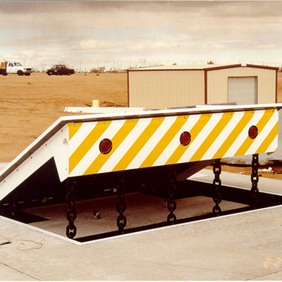
As stated above, the springtime setting up 54 puts in a consistent pressure on the web cam, while the electromechanical actuator may be regulated to exert a variable pressure on the web cam, thereby allowing the training and lowering( i. e., deploying and withdrawing )of the wedge plate 16. In particular embodiments, the constant pressure used by the springtime setting up 54 might be adjustable. g., electromechanical actuator) is handicapped. As will be appreciated, the springtime assembly 54 may be covered and protected from particles or other aspects by a cover plate(e. g., cover plate 68 revealed in FIG. 4) that may be substantially flush with the raised surface area 38 of the structure 14. As discussed above, in the released placement, the wedge plate 16 offers to block accessibility or traveling beyond the obstacle 10. For instance, the barrier 10(e. g., the wedge plate 16 )might obstruct pedestrians or vehicles from accessing you can try this out a property or pathway. As talked about over, the obstacle 10 is affixed to the anchor 30 safeguarded within the structure 14,
front brackets 71. Consequently, the linkage assemblies 72 may pivot and revolve to enable the collapse and expansion of the affiliation assemblies 72 during retraction and release of the bather 10. The affiliation settings up 72 reason movement of the wedge plate 16 to be limited. For instance, if a car is traveling towards the released wedge plate 16(e. For instance, in one address situation, the safety and security legs 86 might be expanded duringupkeep of the barrier 10. When the security legs 86 are released, the safety legs 86 support the weight of the wedge plate 16 versus the surface 12. Therefore, the lifting mechanism 50 may be deactivated, serviced, removed, replaced, and so forth. FIG. 5 is partial viewpoint view of a personification of the surface-mounted wedge-style barrier 10, showing the camera 80 and the cam surfaces 82 of the lifting mechanism 50. Specifically, 2 webcam surfaces 82, which are referred to as lower webcam surfaces 83, are placed listed below the webcam 80. The reduced web cam surfaces 83 might be dealt with to the surface area 12 (e. As an example, the reduced web cam surface areas 83 and the installing plate 85 might develop a solitary item that is secured to the support 30 by bolts or other mechanical fasteners. In addition, 2 camera surface areas 82, which are described as upper camera surfaces 87, are positioned above the web cam 80 and combined to (e. In various other personifications, interfering layers or plates may be placed in between the surface area 12 and the lower web cam surfaces 83 and/or the wedge plate 16 and the upper web cam surfaces 87 As pointed out above, the camera
80 translates along the webcam surfaces 82 when the wedge plate 16 is lifted from the pulled back setting to the released position. Furthermore, as stated over, the spring assembly 54 (see FIG. 3 )might give a force acting upon the camera 80 in the instructions 102 by means of spring pole 58, which may decrease the pressure the electromechanical actuator why not try here 84 is required to put on the cam 80 in order to actuate and lift the wedge plate 16. 1 )to the deployed position(see FIG. 4). As shown, the cam 80 includes track wheels 104(e. g., rollers), which call and equate along the cam surface areas 82 during operation.